The no of LEDs can be increase and decrease according to your requirements and desire. IC Will Blink every Pair one at a time Or In A turn Flop manner.
R3 R4 10 kΩ.
555 flip flop circuit. This type of circuit is used extensively in computers and other digital circuits. For computer applications the 555 is a poor choice for use as a flip-flop. Thats because its output doesnt change fast enough in response to trigger or reset pulses in computer circuits that are driven by high-speed clock pulses.
FLIP FLOP and MEMORY CELL Circuit. When output pin 3 is HIGH the 220n charges through the 220k to 6v. When pin 3 is LOW the 220n discharges through the 220k to 0v.
Pressing the switch upsets the 3v created by the two 10k voltage dividers triggering the flip flop inside the 555 and changing the state of the output from HIGH to LOW or vice-versa. The output of the 555 drives a transistor to turn a globe on and off. IC Will Blink every Pair one at a time Or In A turn Flop manner.
A 10K Variable Resistor Is Used To regulate The Flashing pace consistent with. Flop flop the use of timer ic 555. That is four Volts Circuit And in case you need To Run more LEDs And On 12 Volts Then Use three LEDs In a chain.
The Circuit Given underneath Will boom Your understanding. You could alternate This As want. The circuit is able to blink 8 super bright blue and Reds LEDs.
The circuit is build around a famous 555 timer IC which is wired as an a-stable multi vibrator here. The LEDs are classified in two pairs contains 8 LEDs. The no of LEDs can be increase and decrease according to your requirements and desire.
IC will blink each pair one by one or in a flip flop manner. A 10K variable resistor is used to adjust the flashing speed per. The 555 timer in bistable mode is also known as a flip-flop circuit.
A flip-flop circuit alternates between two stable states in this case the output of electrical current from the output pin. Unlike the monostable mode and astable modes bistable mode doesnt need a resistor and capacitor to set the timing of the circuit. In fact there is no timing in this circuit.
IC NE555 can be used as an oscillator and also as a flip flop element to provide time delay. Two relays are used in the circuit. Relays are switches which electromechanically or electronically open and close the circuit.
Relays track one electric circuit by touch opening and closing in another. Good Day How can I use a 555 as a T flip flop. It needs to toggle at the rising edge of an input that will be active high for 1 hour then active low for 11 hours.
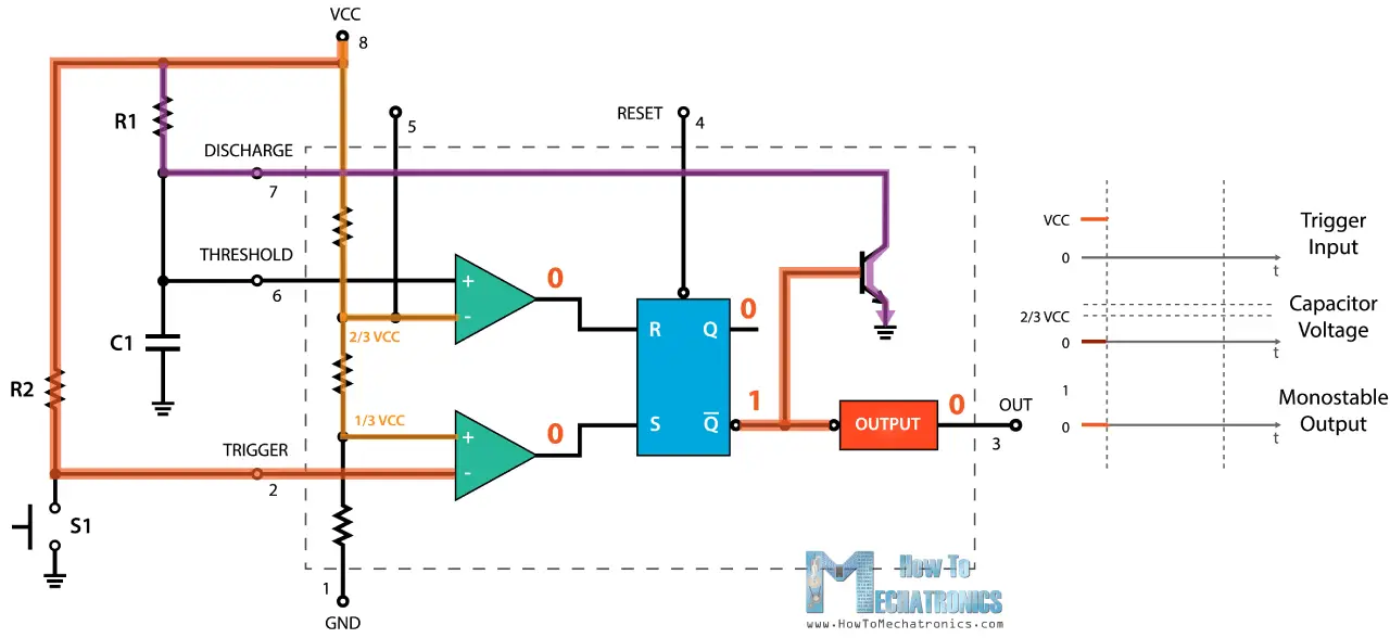
Inside the 555 chip the control function is a implemented by a bistable flip-flop which is switched by the threshold and trigger inputs. A flip-flop does not have to be switched by a clock signal but a latch needs to be enabled. One 555 is set up with a start switch as a one-shot to provide a delay to start the circuit.
Looking back at the schematic for the one-shot R4 charges C2 which is what gives us our delay. Replacing R4 with a potentiometer will allow for a variable delay That triggers the next 555 set up as a flip-flop to output. The 555 timer IC is an integrated circuit chip used in a variety of timer delay pulse generation and oscillator applications.
Derivatives provide two or four timing circuits in one packageIt was commercialized in 1972 by Signetics. Numerous companies have made the original bipolar timers and similar low-power CMOS timers too. In 2017 it was said over a billion 555 timers are produced.
Traffic lights httpsbitly2Qf1ypyflip flop using ic 555 httpsbitly2M1dnkH8 led flahser ic 555. 555 Timer Multivibrator is an electronic circuit that generates square wave rectangular or saw tooth waves. Multivibrators have two state.
Relaxation oscillators timers and flip-flops are all examples of a multivibrator. In this episode Karen continues on in her journey to learn about logic ICs. She started with logic gates then moved onto combination logic devices like mux.
Now when Push button Switch S1 is pressed Trigger PIN 2 goes Grounded Vcc3 and Lower comparator output becomes HIGH for a moment which SETs the flip flop and 555 output is HIGH. 555 remains in this state until the Reset input because now both the comparators are at LOW. 555 Bistable The 555 timer IC can be used with a few simple components to build a bistable circuit also known as a flip-flop.
It is a very simple memory circuit. The circuit is called a bi stable because it is stable in two states. Output high and output low.
The 555 Timer is a precision timing circuit that can produce pulses of accurate and highly stable time delays from microseconds to hours. It is mostly used in practical circuits as flip-flop in monostable bistable and astable forms. From its applications it is known as the IC time machine.
An animated interactive SR latch R1 R2 1 kΩ. R3 R4 10 kΩ. In electronics a flip-flop or latch is a circuit that has two stable states and can be used to store state information a bistable multivibrator.
The circuit can be made to change state by signals applied to one or more control inputs and will have one or two outputs. Heres an example circuit that you can build with the 4013 Dual D Flip-flop IC a coin tosser. The following circuit uses a 555 timer to create a fast-switching clock signal to the flip-flop when you push the button S1.
The inverted output from the flip-flop is connected back to the D input.