IC 555 Timer Monostable Multivibrator Working Explained - Duration. 555 Timer Tutorial Bundle Includes.
You will also use the 555 timer integrated circuit learn how to use a multimeter and tips about soldering.
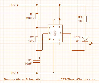
555 timers for dummies. Here are the functions of each of the eight pins. Pin 1 is connected to ground. Pin 8 is connected to the positive supply voltage.
This voltage must be at least 45 V and no greater than 15 V. Its common to run 555 circuits. Pin 3 is the output pin.
The output is either low. Do you want to know how to use a 555 timer. Laura brings you more Back to School tips and tricks on using this integrated circuit555 timerhttpswwwarrow.
In this tutorial we will learn how the 555 Timer works one of the most popular and widely used ICs of all timeFind more on my website. The 555 is one of the most popular integrated circuits ICs ever made. When you use it you need to be aware of the purpose of each of the eight pins in the 555 package.
You may also occasionally use a 556 IC which consists of two 555 timers in a single package and the same applies to knowing its pinouts as well. The 555 timer chip is extremely robust and stable 8-pin device that can be operated either as a very accurate Monostable Bistable or Astable Multivibrator to produce a variety of applications such as one-shot or delay timers pulse generation LED and lamp flashers alarms and tone generation logic clocks frequency division power supplies and converters etc in fact any circuit that requires some form of time control as the list is endless. 555 timers for dummies.
Pin 8 is connected to the positive supply voltage. Then it switches back to the first state and so on ad infinitum. Both the trigger pin 2 and the reset pin 4 inputs are connected to vcc through a 10 kω resistor.
That s because in bistable mode the 555 isn t used as a timer. The 555 can behave as an astable. The 555 timer is used for many things but there are twoclassical circuits that employ the 555 timer at their hearts.
These are the astablemultivibratoraka. Free-running oscillator and the other is the monostableaka. Lets discusseach one in more detail.
555 Timers and the AstableCircuit. A 555 LED Flasher circuit uses an astable multivibrator which produces pulses for flashing the lamp. Two resistors are set in the circuit to control the flashing rate.
A half-wave rectifier a transistor and a TRIAC is used to drive the load. The 555 timer IC is a monolithic timing circuit that produces accurate timing delays and oscillations in a form of a square wave signal. This small IC has a lot of applications such as in oscillators tachometers waveform generators control systems etc.
Some features of 555 timer ICs are. To build a Dark Sensor circuit using 555 timer and LDR which turns on the buzzer in the presence of dark. This project is build using an LDR with 555 timer.
The Buzzer is used as an output indicator in this project. When light falls on the LDR 555 timer process this signal and sends logic 0 to the output ie the buzzer. 555 Timer All ModesHEY YOU ABOUT TO POST SOMETHING STUPIDYes I know my hands are largefat.
Its because of a heart condition I suffer from called Congesti. A standard 555 IC to perform two of its most common functions - as a timer in monostable mode and as a square wave oscillator in astable mode. 555 Timer Tutorial Bundle Includes.
Description Manufacturer PN 1 Standard Timer Single 8-Pin Plastic Dip Tube NE555P 1 400-Point Solderless Breadboard 33L x 21W WBU-301-R 10 Resistor Carbon Film 10kΩ CF14W103JRC. IC 555 Timer Monostable Multivibrator Working Explained - Duration. Akshansh Chaudhary 139236 views.
How to design a transistor circuit that controls low-power devices -. The 555 timer IC is an integrated circuit used in a variety of timer delay pulse generation and oscillator applications. Derivatives provide two or four timing circuits in one package.
It was commercialized in 1972 by Signetics and it was reported to still be in wide use as of 2013. Numerous companies have made the original bipolar timers and similar low-power CMOS timers too. In 2017 it was said over a billion 555 timers are produced annually by some estimates and probably the most popula.
If you dont have a waveform generator consider one of the following options. Arduino- if you have an arduino handy load the code below onto it it will generate a square wave from digital pin 8 that oscillates between 0 and 5V with frequency 500Hz I chose this option 555 timer- wire up a 555 timer to pulse at 500Hz Plug your coaxial cable into the oscilloscope. Connect the center axial portion of the cable to the signal and the side usually an alligator clip to ground.
According to the datasheet for the 555 Timer astable output the following formulas are used this is how the calculator works. Tp 693 Ra Rb C and the Tn 693 Rb C. Electricity For Dummies READ Electricity For DummiesFREE Download file Free Book PDF Electricity For Dummies at Complete PDF Library.
This Book have some digital formats such us. Paperbook ebook kindle epub and another formats. You will also use the 555 timer integrated circuit learn how to use a multimeter and tips about soldering.
Each project has a stripboard or pcb layout plus extra instructions if necessary. Projects instructions are also available as PDF documents for easy printing.