The RC circuit Resistor Capacitor Circuit will consist of a Capacitor and a Resistor connected either in series or parallel to a voltage or current source. The RC circuit Resistor Capacitor Circuit will consist of a Capacitor and a Resistor connected either in series or parallel to a voltage or current source.
Eytan Modiano Slide 2 Learning Objectives Analysis of basic circuit with capacitors no inputs Derive the differential equations for the voltage across the capacitors Solve a system of first order homogeneous differential equations using classical method Identify the exponential solution Obtain the characteristic equation of the system Obtain the natural response of the.
Analysis of rc circuit. An RC circuit is defined as an electrical circuit composed of the passive circuit components of a resistor R and capacitor C driven by a voltage source or current source. Due to the presence of a resistor in the ideal form of the circuit an RC circuit will consume energy akin to an RL circuit or RLC circuit. This post tells about series RC circuit analysis.
RC circuits belong to the simple circuits with resistor capacitor and the source structure. Lets consider series connection of resistor and capacitor with the constant voltage source circuit depicted below. A first-order RC series circuit has one resistor or network of resistors and one capacitor connected in series.
First-order RC circuits can be analyzed using first-order differential equations. By analyzing a first-order circuit you can understand its timing and delays. Here is an example of a first-order series RC circuit.
This guide covers Series RC Circuit Analysis its Phasor Diagram Power Impedance Triangle and several solved examples. Recall that current and voltage are in phase for purely resistive AC circuits while current leads voltage by 90 degrees in purely capacitive circuits. An RC circuit is created when a resistor and a capacitor are connected to each other.
Because a capacitors voltage is in proportion to electric charge q q and the resistors voltage is in proportion to the rate of change of electric charge current i i their interaction within a circuit produces strange results. A simple RC circuit. The key to the analysis is to remember that capacitor voltage cannot change instantaneously.
Assuming the capacitor is uncharged the instant power is applied the capacitor voltage must be zero. Therefore all of the source voltage drops across the resistor. A resistorcapacitor circuit or RC filter or RC network is an electric circuit composed of resistors and capacitors.
It may be driven by a voltage or current source and these will produce different responses. A first order RC circuit is composed of one resistor and one capacitor and is the simplest type of RC circuit. RC circuits can be used to filter a signal by blocking certain frequencies and passing others.
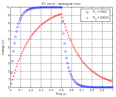
The two most common RC filters are the high-pass filters and low-pass filters. RC Charging Circuit Curves. The capacitor C charges up at a rate shown by the graph.
The rise in the RC charging curve is much steeper at the beginning because the charging rate is fastest at the start of charge but soon tapers off exponentially as the capacitor takes on additional charge at a slower rate. The RC circuit Resistor Capacitor Circuit will consist of a Capacitor and a Resistor connected either in series or parallel to a voltage or current source. These types of circuits are also called as RC filters or RC networks since they are most commonly used in filtering applications.
An RC circuit can be used to make some crude filters like low-pass high-pass and Band-Pass filters. Regarding transient analysis of RC circuit. Ask Question Asked 5 days ago.
Active 3 days ago. Viewed 232 times 1 begingroup Here I am trying to find the input current It and Vct. From my calculation its evident that Vc0Vc0-0V and Vc 10V but I am confused about the first capacitor.
When t0 it acts like a voltage source. Working Out an Equation for the Voltage Across the Capacitor in an RC Circuit Working out the response of a circuit to an input that puts it in an unsteady state is known as transient analysis. Determining an expression for the voltage across the capacitor as a function of time and also current through the resistor requires some basic calculus.
Explains RC circuit analysis for voltage charge and current. This video explains transient analysis of a RC circuit in s-domain. Transient analysis of RC circuit in time involves cumbersome analysis process.
So as to m. This post tells about the parallel RC circuit analysis. RC circuits belong to the simple circuits with resistor capacitor and the source structure.
Lets consider the circuit depicted on the figure below. We have to remember that even complex RC circuits can be transformed into the simple RC circuits. Eytan Modiano Slide 2 Learning Objectives Analysis of basic circuit with capacitors no inputs Derive the differential equations for the voltage across the capacitors Solve a system of first order homogeneous differential equations using classical method Identify the exponential solution Obtain the characteristic equation of the system Obtain the natural response of the.
In an RC circuit connected to a DC voltage source voltage on the capacitor is initially zero and rises rapidly at first since the initial current is a maximum. Vt emf1etRC V t emf 1 e t RC. The time constant τ for an RC circuit is defined to be RC.