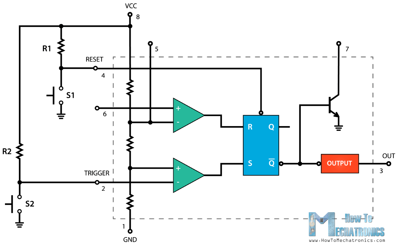
8Power or Vcc Pin 1. Pin 2 is the trigger which works like a starters pistol to start the 555 timer running.

The astable mode is what most people think of when it comes to the 555 timer.
How 555 timer works. Pin 2 is the trigger which works like a starters pistol to start the 555 timer running. The trigger is an active low trigger which means that the timer starts when voltage on pin 2 drops to below one-third of the supply voltage. When the 555 is triggered via pin 2 the output on pin 3 goes high.
The working principle of the 555 timer is by considering the block diagram of the 555 timer IC. The first comparator has threshold input to pin 6 and control inputs for pin 5. The control input is used in some of the applications but most of the applications the control input is not used hence the control voltage is equal to 23 Vcc.
In short the 555 timer chip works by detecting threshold voltage levels. Pin 2 detects a voltage below 13 of the supply voltage to turn the IC on. And pin 6 detects a voltage above 23 of the supply voltage to turn the IC off.
When we connect the IC to the supply the capacitor C1 begins to charge through R1 and R2. 555 Timer IC - how it works Internally the 555 Timer IC encloses two comparators one flip-flop circuit and two NPN transistors. Before going into 555 Timer workflow we should explain how a comparator or a SR latch aka flip-flop works.
The comparator is an IC that has at least 5 pins. V CC GND V IN V IN - and the OUTput pin. IC 555 timer is a one of the most widely used IC in electronics and is used in various electronic circuits for its robust and stable properties.
It works as square-wave form generator with duty cycle varying from 50 to 100 Oscillator and can also provide time delay in circuits. How Does 555 Timer Work The trick to understanding how the 555 timer works is to begin by understanding the SR flip-flop operation logic. Asserting the SET function makes Q1 and Q0.
This state remains until the assertion of the RESET function which makes Q0 and Q1. This is a astable 555 timer circuit. 555 timer ic is a very useful and largely used in practical life so this video is about its basic operation.
The 555 timer is a chip that can be used to create pulses of various durations to output a continuous pulse waveform of adjustable pulse width and frequency and to toggle between high and low states in response to inputs. By wiring the 555 timer with resistors and capacitors in various ways you can get it to operate in three different modes. 555 Timer Pin Diagram and Descriptions.
Now as shown in figure there are eight pins for a 555 Timer IC namely 1Ground. 8Power or Vcc Pin 1. This pin has no special function what so ever.
It is connected to ground as usual. The basic 555 timer gets its name from the fact that there are three internally connected 5kΩ resistors which it uses to generate the two comparators reference voltages. The 555 timer IC is a very cheap popular and useful precision timing device which can act as either a simple timer to generate single pulses or long time delays or as a relaxation oscillator producing a string of stabilised waveforms of varying duty cycles from 50 to 100.
The 555 timer IC is an integrated circuit chip used in a variety of timer delay pulse generation and oscillator applications. Derivatives provide two or four timing circuits in one packageIt was commercialized in 1972 by Signetics. Numerous companies have made the original bipolar timers and similar low-power CMOS timers too.
In 2017 it was said over a billion 555 timers are produced. The two main versions of the 555 timer IC are the SE and NE versions. The only difference between the two versions is that the SE version can operate comfortably within the temperature -55 o C to 125 o C while the NE operates very well within temperature of 0 to 70 o C.
As we have seen previously the 555 timer comes as a single device within an 8-pin dual-in-line package DIP or as the 556 device which has two 555 chips in a single 14-pin dual-in-line package. The two 555 timers within the 556 operate independently of each other but share a common V CC supply and ground 0V connection. 555 timer IC works from a wide range of power supplies ranging from 5V to 18V.
Sourcing or sinking load current is 200mA. The external components must be selected correctly so that the timing intervals can be completed in several minutes along with the frequencies beyond several hundred kHz. 555 Timer IC-Block Diagram Working Pin Out Configuration Data Sheet A complete basic tutorial.
This article covers every basic aspect of 555 Timer IC. You may already know that SENE 555 is a Timer IC introduced by Signetics Corporation in 1970s. In this article we cover the following information about 555 Timer IC.
Astable Mode of the 555 Timer. The astable mode is what most people think of when it comes to the 555 timer. Many times when you see a project with flashing LEDs its a 555 timer at work.
But it has a lot of other interesting applications too. For example it can also generate frequencies to produce sound when the output is connected to a.