Numerous companies have made the original bipolar timers and similar low-power CMOS timers too. You can find here some circuits based on 5555 IC.

Two relays are used in the circuit.
Ic 555 flip flop. For computer applications the 555 is a poor choice for use as a flip-flop. Thats because its output doesnt change fast enough in response to trigger or reset pulses in computer circuits that are driven by high-speed clock pulses. For computer applications better flip-flop chips are readily available.
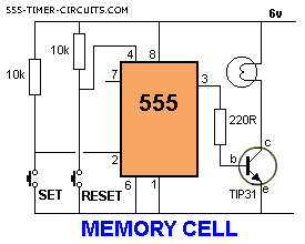
FLIP FLOP and MEMORY CELL Circuit. When output pin 3 is HIGH the 220n charges through the 220k to 6v. When pin 3 is LOW the 220n discharges through the 220k to 0v.
Pressing the switch upsets the 3v created by the two 10k voltage dividers triggering the flip flop inside the 555 and changing the state of the output from HIGH to LOW or vice-versa. The output of the 555 drives a transistor to turn a globe on and off. IC Will Blink every Pair one at a time Or In A turn Flop manner.
A 10K Variable Resistor Is Used To regulate The Flashing pace consistent with. Flop flop the use of timer ic 555. That is four Volts Circuit And in case you need To Run more LEDs And On 12 Volts Then Use three LEDs In a chain.
The Circuit Given underneath Will boom Your understanding. You could alternate This As want. For a 555 timer working as a flip flop or as a multi-vibrator it has a particular set of configurations.
Some of the major features are as follows. Sinking or sourcing 200 mA of load current. It operates from a wide range of power ranging from 5 Volts to 18 Volts supply voltage.
The output of a 555 timer can drive a transistor-transistor logic TTL due to its high current output. Traffic lights httpsbitly2Qf1ypyflip flop using ic 555 httpsbitly2M1dnkH8 led flahser ic 555. The 555 timer in bistable mode is also known as a flip-flop circuit.
A flip-flop circuit alternates between two stable states in this case the output of electrical current from the output pin. Unlike the monostable mode and astable modes bistable mode doesnt need a resistor and capacitor to set the timing of the circuit. In fact there is no timing in this circuit.
Traffic lights httpsbitly2Qf1ypy flip flop using ic 555 httpsbitly2M1dnkH 8 led flahser ic 555 httpsbitly2M1dnkH in this video I have made a f. How can I use a 555 as a T flip flop. It needs to toggle at the rising edge of an input that will be active high for 1 hour then active low for 11 hours.
Bistable mode it is also known as flip-flop mode. It has both stable states. Two different trigger inputs are applied to change the state from high to low and low to high.
It is used in automatic switching applications to generate pulse of variable time etc. Circuit Diagram of 555 IC in Astable Mode. The 555 timer IC is an integrated circuit chip used in a variety of timer delay pulse generation and oscillator applications.
Derivatives provide two or four timing circuits in one packageIt was commercialized in 1972 by Signetics. Numerous companies have made the original bipolar timers and similar low-power CMOS timers too. In 2017 it was said over a billion 555 timers are produced.
The single 555 Timer chip in its basic form is a Bipolar 8-pin mini Dual-in-line Package DIP device consisting of some 25 transistors 2 diodes and about 16 resistors arranged to form two comparators a flip-flop and a high current output stage as shown below. The standard Timer action of the IC 555 is initiated by introducing a 0 V trigger pulse at pin 2. This 0V pulse being below the 13rd level of the DC supply voltage or the Vcc forces the output of the trigger comparator to change state.
Due to this the RS flip-flop also changes its output state turning off Q6 and driving OUTPUT pin 3 high. The 555 Timer IC is an integrated chip used in a variety of timer pulse generation and oscillator applications. The 555 Timer IC is used to provide time delays as an oscillator and as a flip-flop element.
Two other packages of the Timer ICs are available which are 556 and 558. Nodesummary555 Timer IC is one of the commonly used IC among students and hobbyists. There are a lot of applications of this IC mostly used as vibrators like ASTABLE MULTIVIBRATOR MONOSTABLE MULTIVIBRATOR and BISTABLE MULTIVIBRATOR.
You can find here some circuits based on 5555 IC. This tutorial covers different aspects of 555 Timer IC and explains its working in. IC NE555 can be used as an oscillator and also as a flip flop element to provide time delay.
Two relays are used in the circuit. Relays are switches which electromechanically or electronically open and close the circuit. Relays track one electric circuit by touch opening and closing in another.
Then connect the 12V battery with the circuit. Positive on a common pin of relay and negative pin on the coil. In this heading we will discuss the circuit operation of the Dual-LED Flasher relay.
However in this circuit we have used a few low-cost components and it is the easiest LED flasher circuit available on the internet. The name JK flip-flop is termed from the inventor Jack Kilby from texas instruments. Due to its versatility they are available as IC packages.
The major applications of JK flip-flop are Shift registers storage registers counters and control circuits. Inspite of the simple wiring of D type flip-flop JK flip-flop has a toggling. In this IC there are two comparators which is meant to compare incoming voltages.
These comparators drive a RS flip flop and this in turn activates a discharge transistor. A capacitor will be connected to this pin. Output from Flip flop will will be inverted to the output pin of 555 IC.